Introduction
Crashworthiness is, together with Ride and Handling, NVH, Durability, one of 4 key aspects when designing a vehicle. Finite element analysis plays a very important role when it comes to crashworthiness. Since performing real crash tests is extremely costly it is not a surprise that the industry is relying more and more on the numerical analysis. This study covers the impact analysis of the frontal crash tube on the middle size commercial vehicle. The focus was to observe the collapse of the tube, which took place during the frontal impact. Besides that, we were also interested in the force-displacement curve and the acceleration on the chassis.
Geometry and mesh
The front impact tube was extracted from the global model of the chassis, which is sown on the figure below.
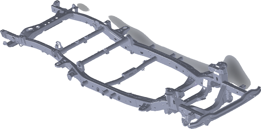
The entire modal of the chassis contains a lot of areas that are not important for the crash analysis. This is why we reduced the geometry to the frontal area of the chassis only.
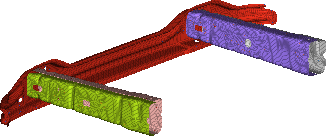
The front impact tube was made of sheet metal, which meant that we could model it with shell elements. The explicit scheme would be used for this analysis so we needed to pay attention to the meshing. Since the simulation resulted in highly distorted elements, we needed to ensure the element deletation was appropriately set up. Plastic material properties were used, together with damage criteria to model cracking of the material.
Loads and Boundary conditions
Initial velocity was prescribed to the vehicle. The mass of the vehicle was simplified with a point mass at the center of gravity. The rigid wall was constrained in all degrees of freedom.
Results
To see the deformation of the crash tubes during the impact, we plotted the plastic deformation at different time increments
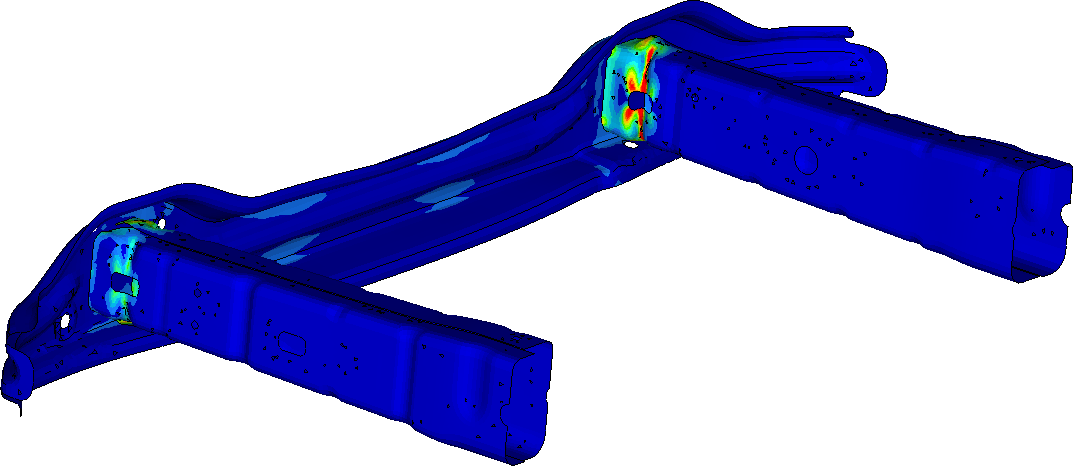
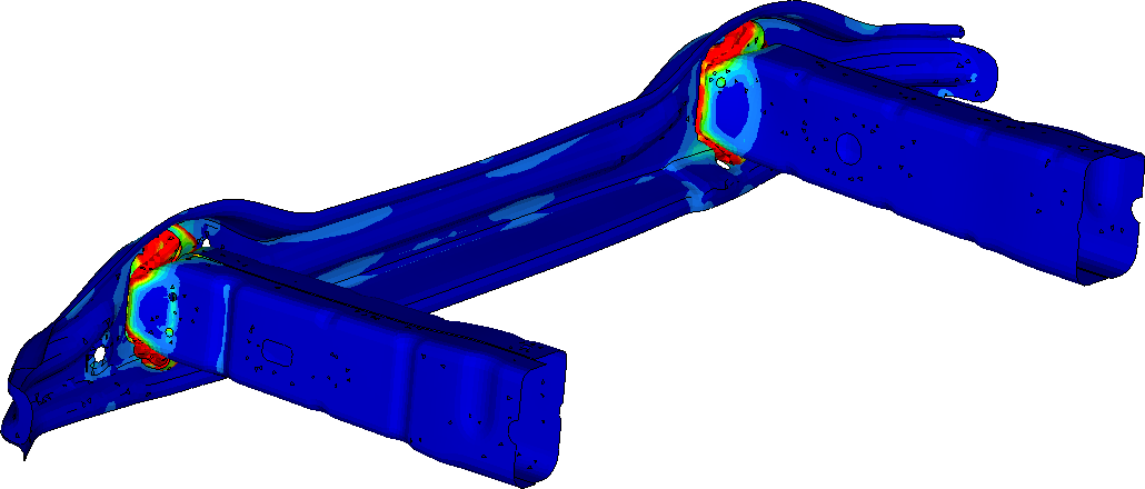
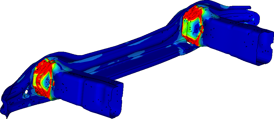
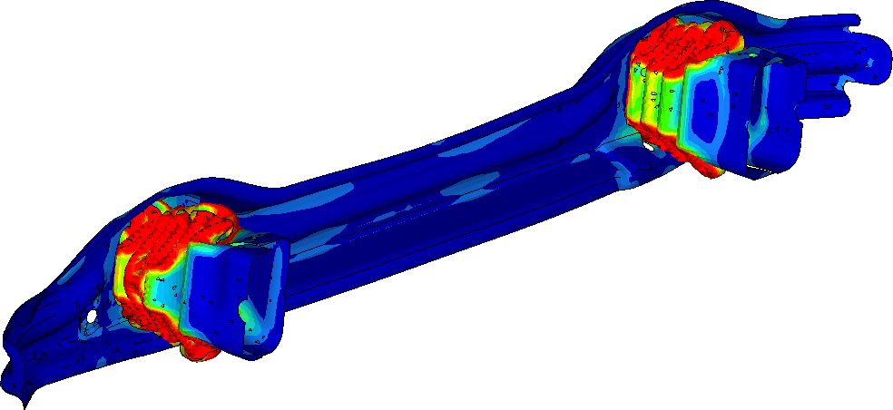
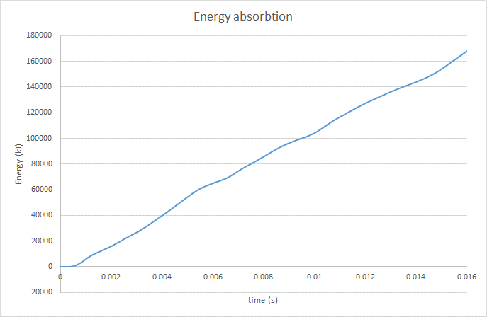
It can be seen that the crash tube is designed to absorb as much energy as possible. This absorbed kinetic energy is stored in the plastic deformation of the material.
On figure 4, the reader can also observe the force-deflection curve and the acceleration.