
Introduction
Structural vibrations are an important subject in modern day engineering. The response of the structures, subjected to different kinds of dynamic loading, can lead to very specific behavior. There are not many branches in engineering where vibrations would be as important as they are in aerospace. The main objective of this paper was the study of a vibration of a second stage compressor blade in the Rolls-Royce Trent 900 turbojet engine due to the blade tip-rubbing. Blade tip-rubbing is an event that can take place in the core of the jet engine during sever external loading. In pursue of ever increasing efficiency of the turbo engines, the tips of the compressor blades are rotating only a few tents of a mm away from the stationary casing of the engine. Under severe loading this casing, which is initially round, can deform in somewhat elliptic shape. This deformation of the casing can, in critical situations, be greater than the spacing between the tip of the compressor blade and the casing. This would mean that the blades would rub against the casing on two parts on the circumference, 180 deg apart.
- The FE modeling of a second stage compressor blade in TRENT 900 Rolls-Royce jet-fan
- Pre-stress calculation of this compressor blade, due to the rotational velocity
- Eigenvalue analysis of the pre-stressed compressor blade
- FE modeling of the deformed casing surrounding the compressor blade
Since blade-tip rubbing is a highly nonlinear event, explicit finite element scheme is the only one that would be capable of such calculation
Geometry and mesh
Although this study contains different Finite element models, only the model containing blade tip rubbing simulation will be presented in more detail.
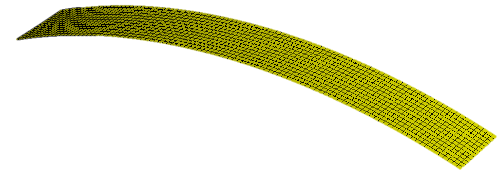
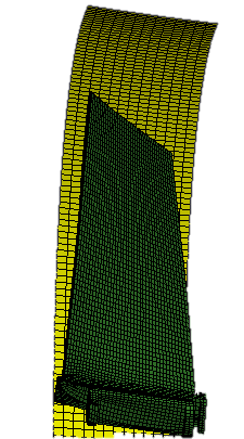
Model of the Compressor blade
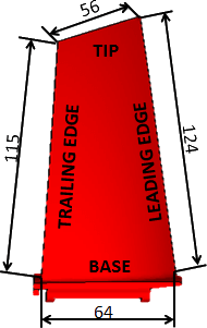
This geometry needed to be appropriately meshed. From the very beginning of the activity, the demand was to build the compressor blade using solid elements. Although the blade has, especially near the tip of the blade, quite a poor aspect ratio, solid elements were still chosen instead of shell elements. The fact is that transverse shear needed to be modeled and the only way to do that was to use solid elements.
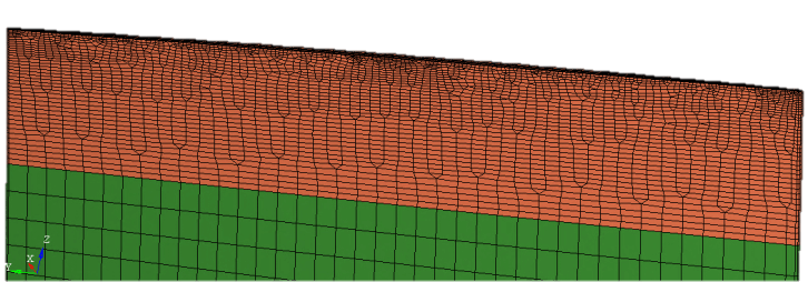
As we were carrying out various blade tip rubbing simulations later in the project, the highest stresses were captured at the tip of the blade as an influence of the contact between the blade and the casing. Our goal was to capture these stresses as accurately as possible which is why the tip of the blade needed to be remeshed. The behavior of the blade turned out to be a bit more accurate compared to the one of the original mesh.

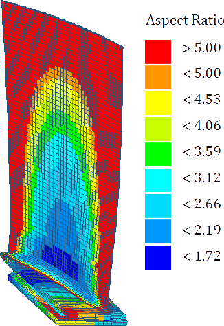
The element is considered to have poor aspect ratio when its value is more than five. This kind of geometric properties can lead to the event of so the called shear locking. This type of locking in the fully integrated element produces additional stresses only on the larger sides of the element. This added stress makes the element appear stiffer than it really is. This shear locking can, for instance, lead to higher natural frequencies in the structure. To avoid shear locking fully integrated solid elements with poor aspect ratio were used.
Modeling of the turbine casing
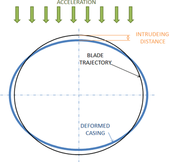
Throughout everyday operation, turbofan engines undergo high accelerations. These accelerations are mainly present at the time of landing, taking off or hard maneuvering while in the air. Looking at the Figure, under the influence of these high acceleration the casing in turbofan engine deforms in elliptic shape.This shape leads to the fact, that there are only two parts around the casing that intrude into the blades trajectory, which means there are only two parts where the tip-rubbing takes place. Goal for our project was to capture this deformed elliptic shape of the casing within the FE model, to simulate blade tip-rubbing as accurately as possible.
Loads and Boundary conditions
The main loading on the compressor blade during the rotation comes in form of the centrifugal force. This makes the blade in contact with the disc only at the upper part of the base. For modeling of this kind of contact, the constraint showed in Figure 6 seemed most realistic. The rotational speed was set to be 8500rpm.
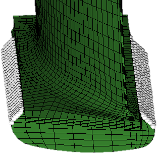
The nodes which are highlighted in Figure 6 were also constrained in all the degrees of freedom except the rotation around the x-axis.
Pre-stress calculation on the compressor blade
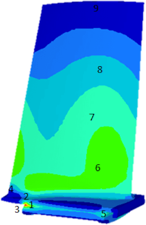
The initial conditions at operating rotational velocity needed to be set for the transient explicit analysis. A sudden increase in velocity can cause stresses, that would make our simulation inaccurate further on, or even crash. The simulation where the blade would start from a steady state and accelerate to the targeted velocity would be very inefficient and time consuming, which is why the initial stress-strain conditions were first calculated implicity (static) with the prescribed centrifugal force. This stress-strain conditions were later imported into the first step of the explicit simulation. Stresses due to the centrifugal force can be seen on Figure 7
Natural frequencies
After the blade model had been pre-stressed, it was time to find blades’ natural frequencies. As we expected, the natural frequencies of the system would change, if the system would undergo a certain amount or stress. Looking at the compressor blade after the pre-stress, it can be stated that:
- Pre-twist in the blade had lowered
- Bending stiffness of the blade, because of the tension, had increased
Tip Rubbing Simulation
Once the natural frequencies and pre-stress due to the centrifugal force have been obtained, it was time to perform full tip rubbing simulation with 5 rubbings. The rubbing event can be seen on the Figure 9.
It can be observed, that there were five increases in the sliding energy in Figure 10 which indicated five rubs. Due to friction, the energy rose even more as the simulations got longer. Since we know that the friction coefficient was more or less constant for all the sliding conditions, the only cause for the even more increasing Sliding energy could be because of the increase of the normal force.
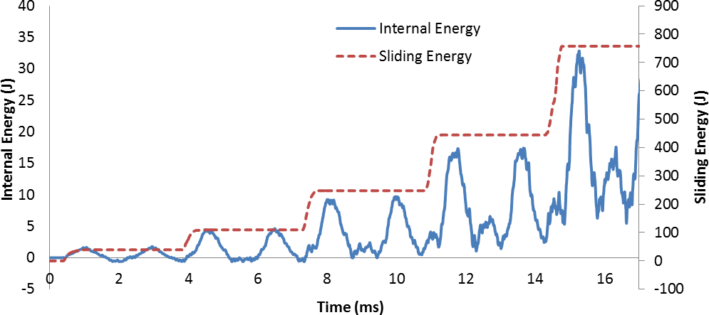
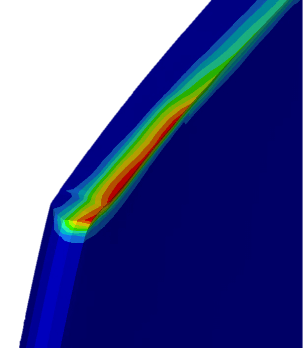
Looking into the graph of the Internal energy in Figure 10, one can spot a number of patterns. The most obvious one is that the internal energy increased as the simulation got longer. Furthermore, we can observe two peaks in between each rub. As said before, the peak of the Internal energy appears when the deformation is at its largest. This indicated that there had to be two peak displacements in between each rub. Looking towards the end of the simulation, it can also be seen, that after the last two rubs, the energy did not reach zero point anymore. This was due to the fact that the Internal energy was stored in the plastic deformation of the blade. In Figure 11, the leading edge at the tip of the blade after the forth and the fifth rub can be seen.
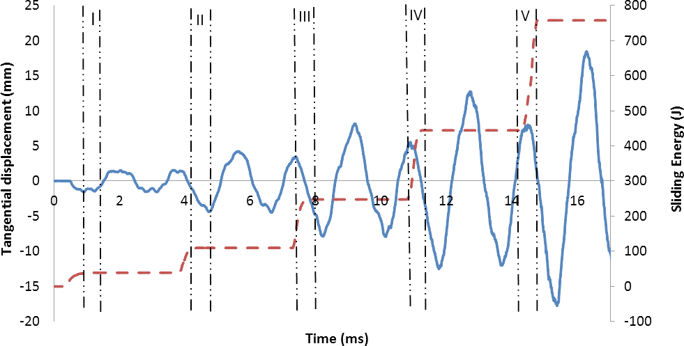
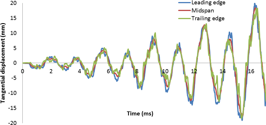
For a better representation of the exact time of each rub, the curve representing the sliding energy has also been added to the graph of the tangential displacement in Figure 12. All five rubs are indicated with the Roman numerals. Same as in the Internal energy graph, a number of patterns can be observed
- The amplitudes of tangential displacement get higher as the simulation gets longer
- There is a certain harmonic motion to the tip of the blade
- There are two peak amplitudes in between two rubs
The first observation aligns with the fact that the Internal energy in the structure got higher with each rub. It can also be observed, that the rate of the increase in the peak displacement amplitude got lower. This can be explained with the fact that after the forth rub, not all the Internal energy was stored in the elastic deformation as the plastic deformations occurred.
The second observation, gained from the tangential displacement graph, was that there was a certain harmonic motion present in the blade while tip-rubbing. We can back up this statement by looking at Figure 13.
The main vibrational mode can clearly be identified from Figure 14. In order to obtain the frequency of this vibration and indeed all the other natural frequencies present, the Fourier transformation of the midspan tangential displacement signal was carried out.
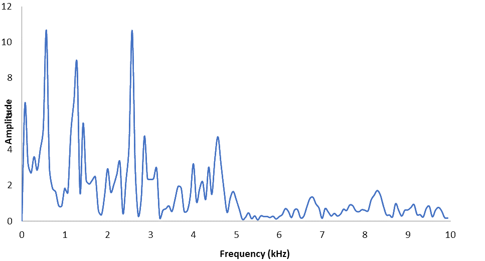
Looking at the presence of vibrations at higher frequencies, two main peaks can be observed. One of them identifies the second bending mode, while the other belongs to the first combined flexural-torsional mode. If we were to compare the values obtained with the Eigenvalue simulation.
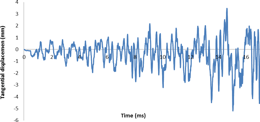
After analyzing the bending vibrations of the compressor blade, we wanted to identify the torsional vibrations as well. The idea was, to take the tangential displacements of the leading and the trailing edge at the tip of the blade and subtract them. By doing so, relative motion between the leading and the trailing edge would be obtained. The subtraction of both curves can be seen on Figure 15.
Performing Fourier transformation of the signal on Figure 15 should identify the torsional natural frequencies. This transformation is presented on Figure 16.
The first peak on the Figure 16 still belongs to the first bending mode. Going further up the frequency scale, the first three torsional frequencies are very well identified. The accuracy between the transformed displacement signal and the Eigenvalue simulation was very good for first two torsional frequencies.


