Introduction
This study covers the collapse of the reinforced panel under the buckling load. A reinforced panel has a "honeycomb" structure, which gives it a high load-carrying capacity. These types of structures are widely used in the aerospace and automotive industry. Many different types of buckling can occur in the reinforced panel like that. To name a few: plate buckling, inter rivet buckling, fastener buckling. As part of the study, we were also interested in the post-buckling effects, which implied the use of nonlinear finite element method.
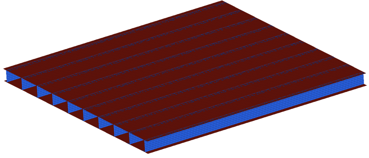
Geometry and mesh
The dimensions of the panel are 500x500x25. Since the entire structure is thin-walled, shell finite elements were used. For better stress convergence, we used second-order shell elements. The top and bottom plates were connected to the reinforced fasteners via the rivets. These rivets were modelled as rigid elements with equal spacing. The material used for the entire structure, was 6082 aluminum. Plasticity was also considered in the material characterization for later nonlinear analysis.
Loads and Boundary conditions
In the initial step, linear buckling was calculated. This step gave us the eigenvalues in the form of axial force, and normal modes in the form of buckling shapes. In the second step, these linear buckling shapes were used for incorporating imperfections into the structure. With the help of these imperfections, the post-buckling collapse would be initiated.
Results
Results of the linear buckling provide the buckling forces and the buckling modes. Post-buckling results illustrate the collapse of the panel that follows.
Linear buckling
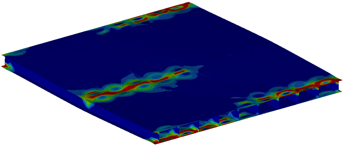
We can see the first and the second buckling mode on the figures 2 and 3.
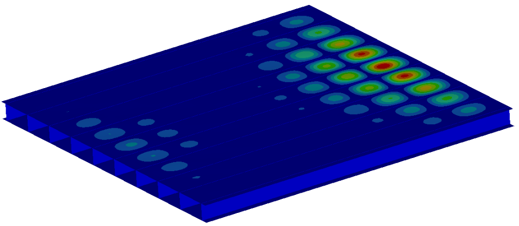
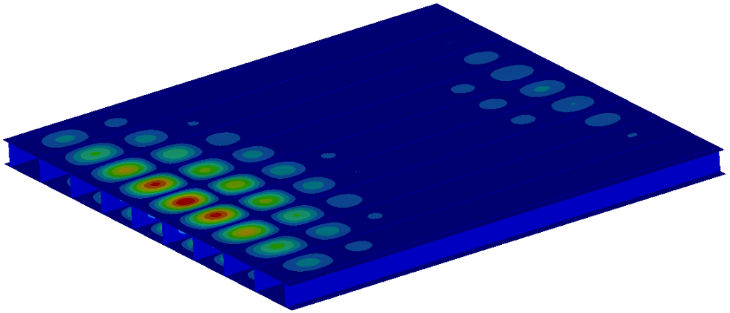
This type of buckling is identified as plate buckling. The forces at which these two buckling modes occur are:
- F1=525kN
- F2=526kN
Post-buckling
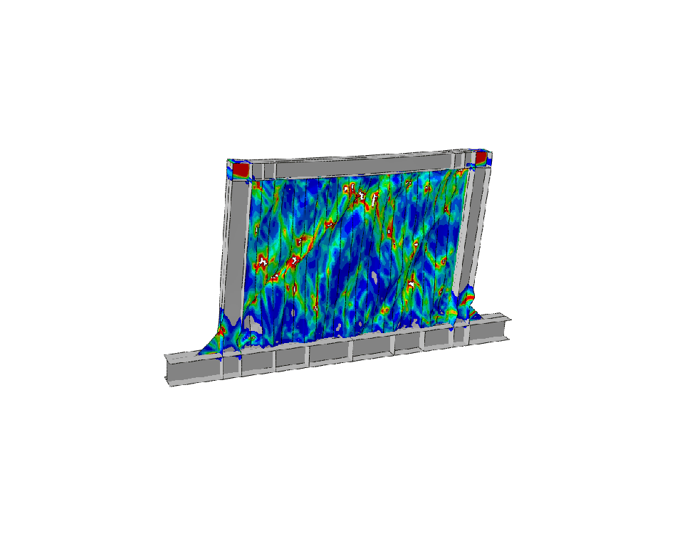
During the post-buckling, we were mainly interested in the decrease of the load-carrying capability of the panel.
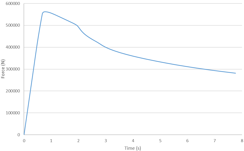
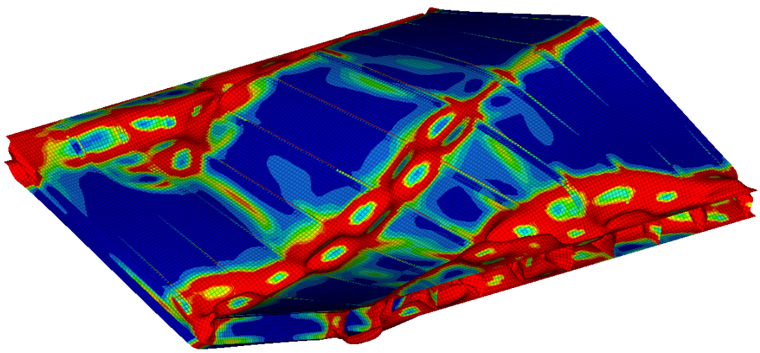
The figure nicely illustrates that the top and bottom plates started to buckle first, follower by the buckling in the fasteners. The reader can observe how load-carrying capability decreased, as the collapse progressed. The shape of the entirely buckled structure at the end of the simulation, can be seen in the figure below.
Conclusion
Using the finite element analysis we were able to predict the buckling collapse of the reinforced panel. It is important to understand also the behavior of the structure, even after the collapse has started since we might be able to detect the failure during the operation. If we needed to increase the load-carrying capability of such a panel, we could achieve that by increasing the thickness of the upper and lower plate or decrease the spacing between the fastener.