.png)
Introduction
Forming is one of the most widely used manufacturing processes in the industry. It is suitable for high volume production of sheet metal components. The type of forming we are interested in is called deep drawing.
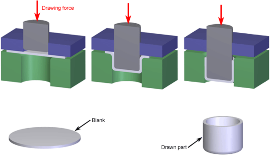
Deep drawing is a sheet metal forming process in which a sheet metal blank is radially drawn into a forming die by the mechanical action of a punch. It is thus a shape transformation process with material retention. The flange region experiences a radial drawing stress and tangential compressive stress due to the material retention property. These compressive stresses can result in flange wrinkles. Wrinkles can be prevented by using a blank holder, the function of which is to facilitate controlled material flow into the die radius. Many parameters influence the quality of a deep drawing. One of the most important is the force with which the holder is pressing the blank against the die during the process.
GEOMETRY AND MESH
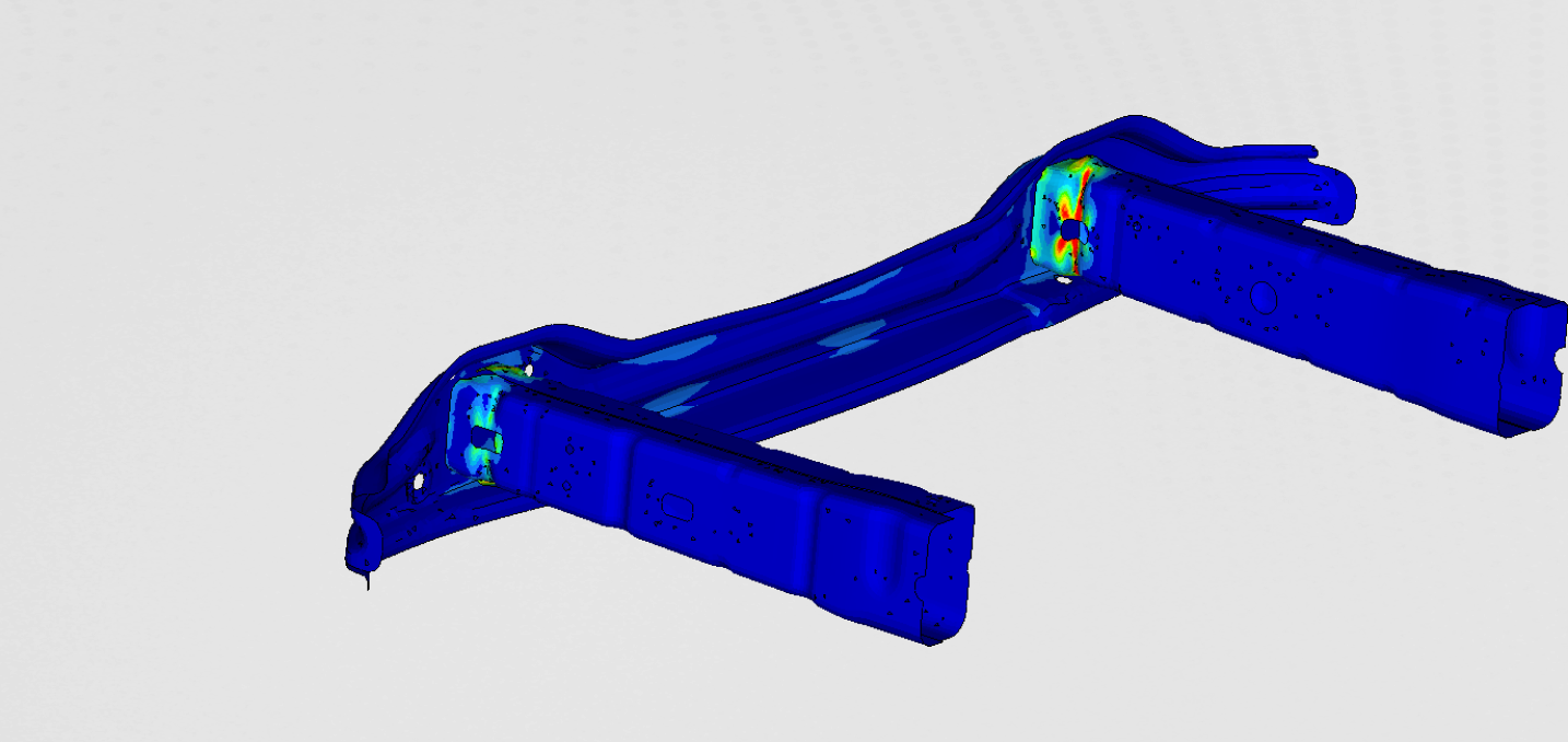
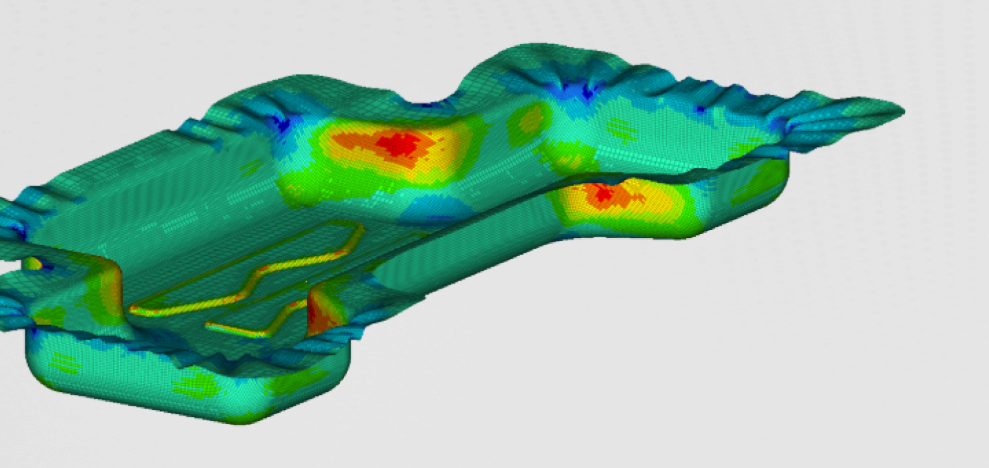
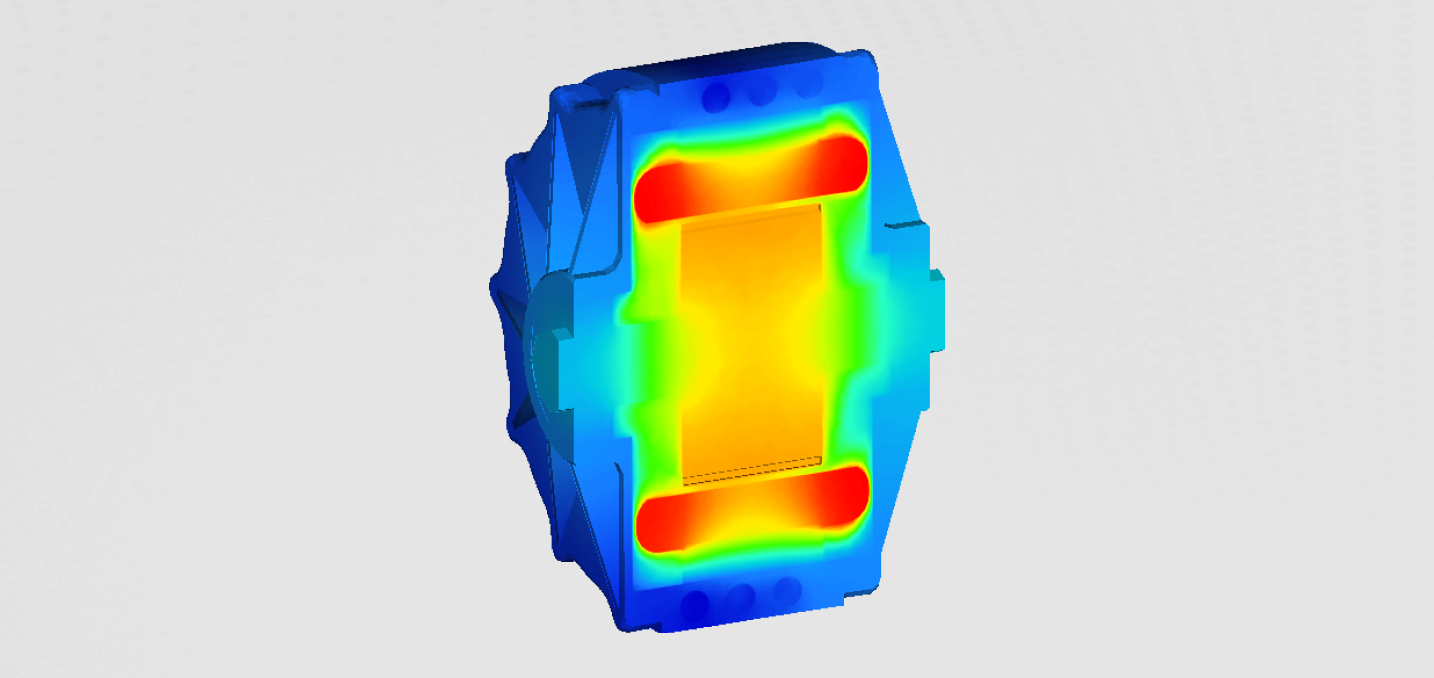
The final shape of the forming process is presented in the Figure 2
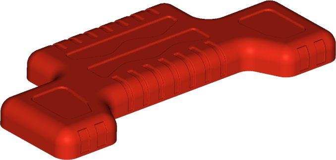
The features on the sidewalls of the muffler were suppressed and can be performed with additional forming later in the manufacturing process.
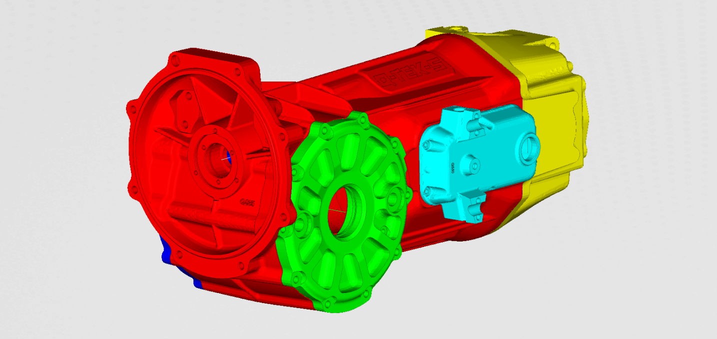
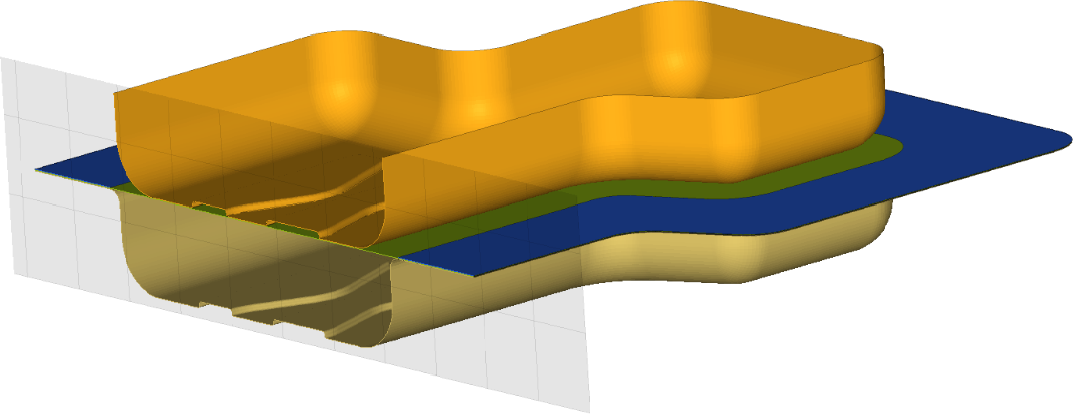
To perform the deep drawing simulation, all four main parts had top be modelled. All the parts, apart from the metal sheet, were modeled as rigid. Metal blank is modeled with shell elements. The simulation uses an explicit scheme. Using automatic remeshing and mass scaling, we were able to find a good compromise between performance and accuracy. With automatic remeshing, we could mesh the blank as very coarsely in the beginning. As the simulation progressed, the algorithm refined the mesh on the location where large strains occurred. Additionally, automatic mass scaling helped us keep the time step in the optimal range.
LOADS and BOUNDARY CONDITIONS
Force on the holder, together with the speed and travel distance of the punch, was the only loads and boundary conditions needed.
The material properties also play an important role in forming simulation. The Forming limit curve was used to correctly characterize the material of the blank. This curve characterizes the relation between the Major and Minor strain.
Results
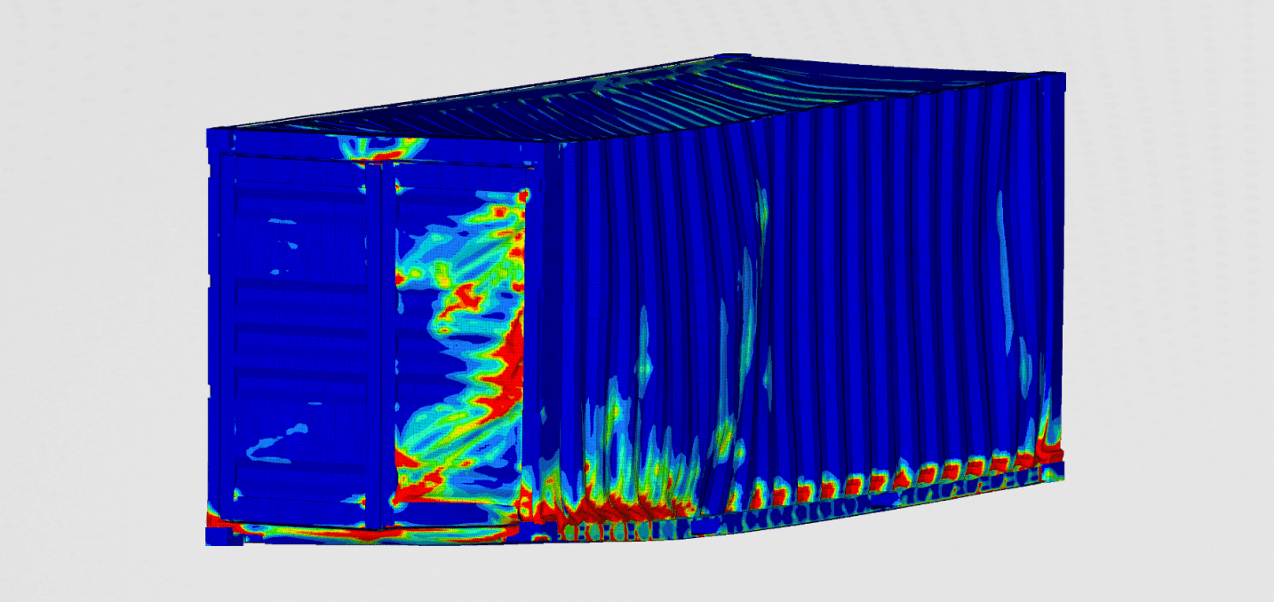
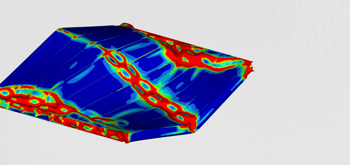
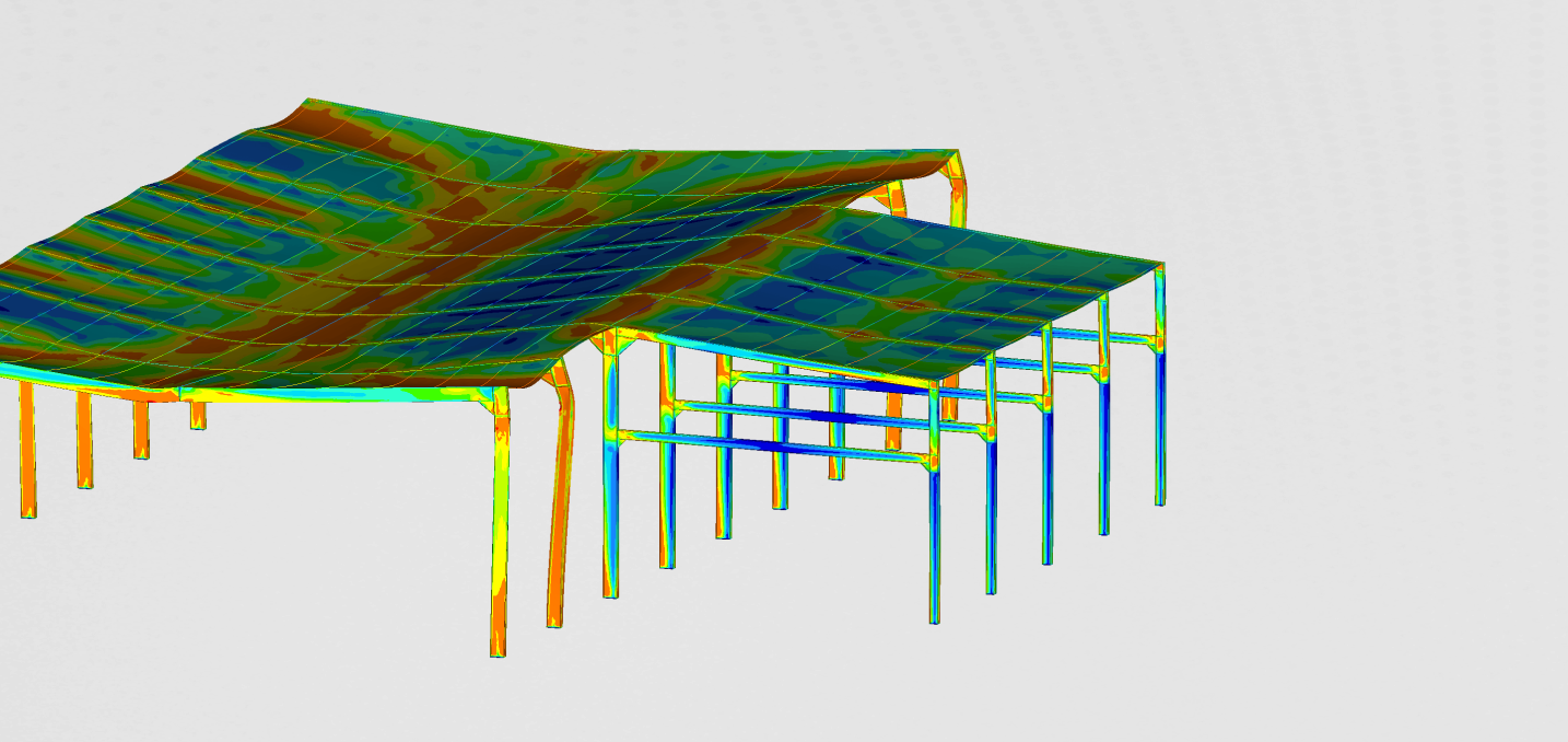
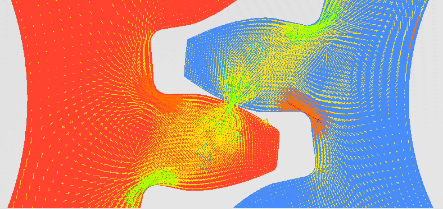
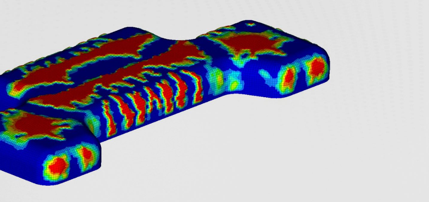
In Figures 4 and 5, we can see how the holder force can prevent wrinkling at later stages of deep drawing. On the other hand, a larger holder force introduces larger stresses and a higher amount of thinning in the material. It is crucial to find just the right amount of force to prevent wrinkling and at the same time keep the thinning and the stresses as low as possible.
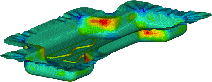
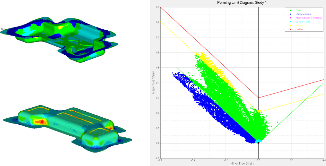
To observe the forming process in detail, forming the Limit curve is plotted.
CONCLUSION
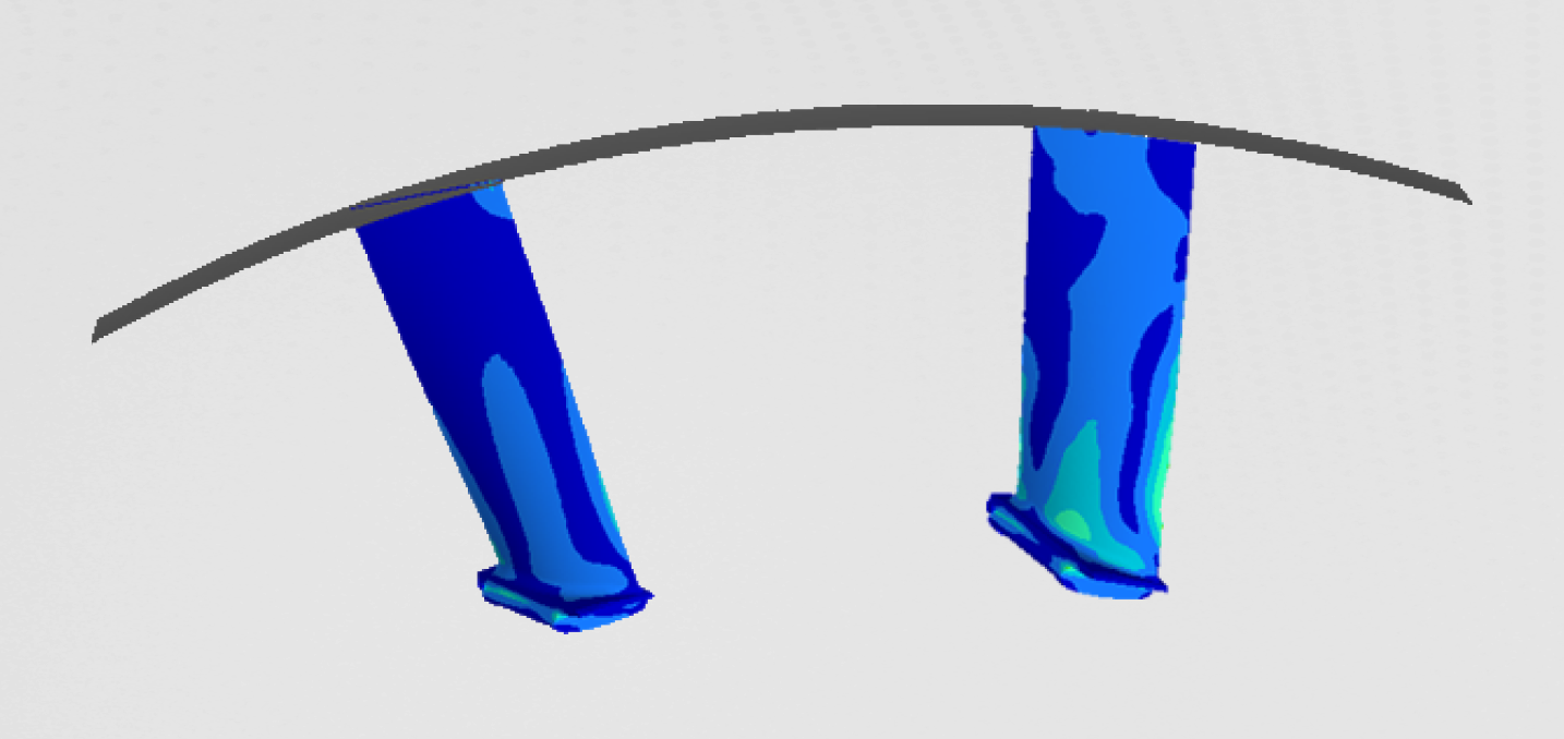
Choosing the appropriate holder force and the right friction coefficient is crucial for the deep drawing process. With only 10kN of holding force, the holder was lifted by the compression of the blank. The compression in the blank results in the buckling of the sheet metal. We can overcome this issue by increasing the holder force. This can solve the problem of wrinkling, but at the same time introduces more stress in the blank.