Introduction
Spur gears are widely used throughout all branches of industry for transferring torque and power. Precision manufacturing and advanced lubrication increase the efficiency of the power transition. Alongside efficiency, durability and weight optimization are some of the main focuses in the gear design. With the use of the transient finite element method, we can study the behavior of the gears during different operating conditions.
When designing spur gears, we are mostly interested in stresses on the teeth during the operation. These stresses set us the limit of how much torque and power spur gear can transmit. Another important aspect of spur gear design is the study of the connection between the gear and the shaft.
There are many types of torque transfer interfaces. One of the most desirable is the press-fit or interference-fit connection. A press-fit is a form of torque transfer technique between the gear and the shaft, where all the torque is transmitted with friction between two parts. This type of connection is very compact and does not require any additional parts.
Geometry and mesh
To make the analysis more manageable, a plane stress state was used. This simplified the finite element model and enabled us to have a detailed mesh and high stress resolution.
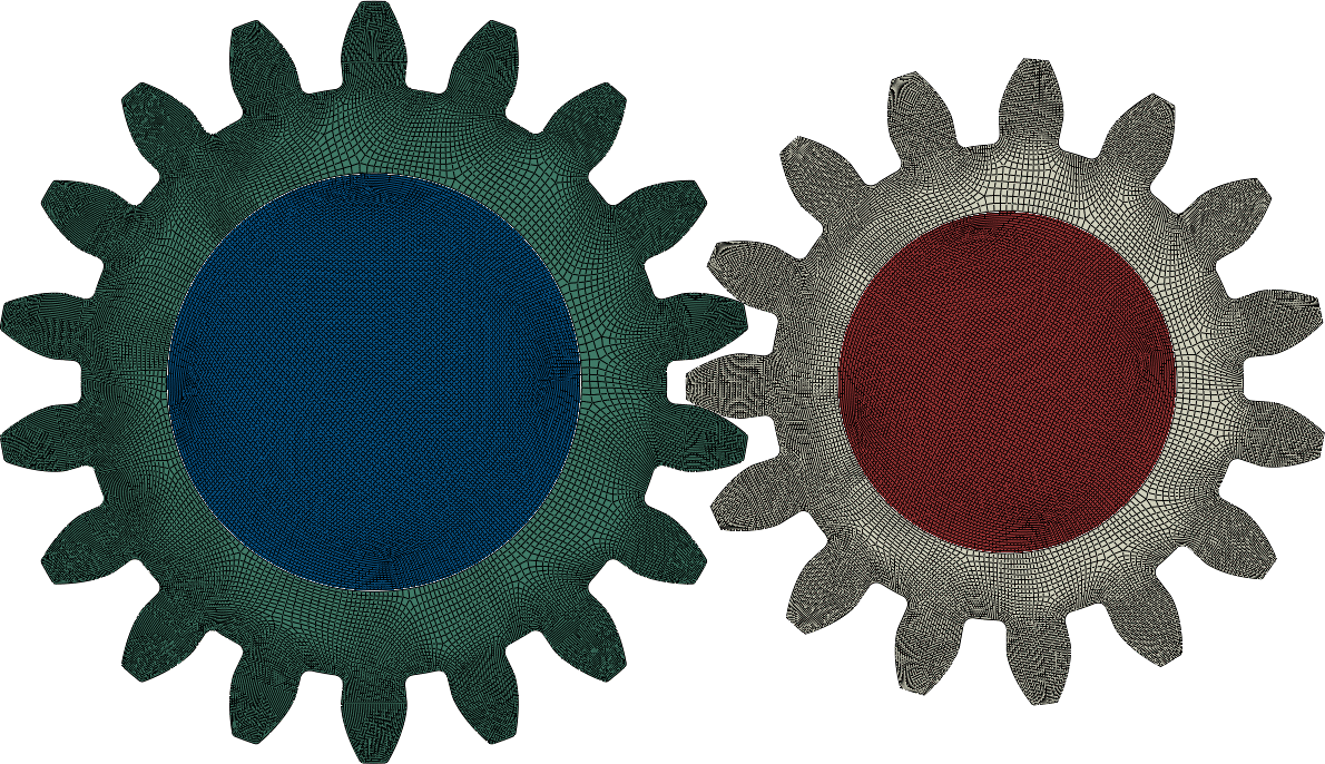
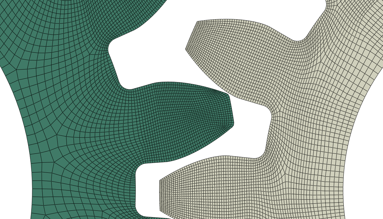
The mesh was refined towards the end of the teeth for better convergence of the stresses in the contact.
Loads and Boundary conditions
In the initial step, when the press-fit was calculated, no external loading acted on the gears. The stress was present only due to the interference between the parts. The interference between the shaft and the hear was 0.2 mm. This interference would ensure the transfer of 1000Nm of torque with the safety factor of 2. In the second step, torque was prescribed to both gears. Since the simulation contained complex contacts, an explicit scheme was chosen for the analysis
Results
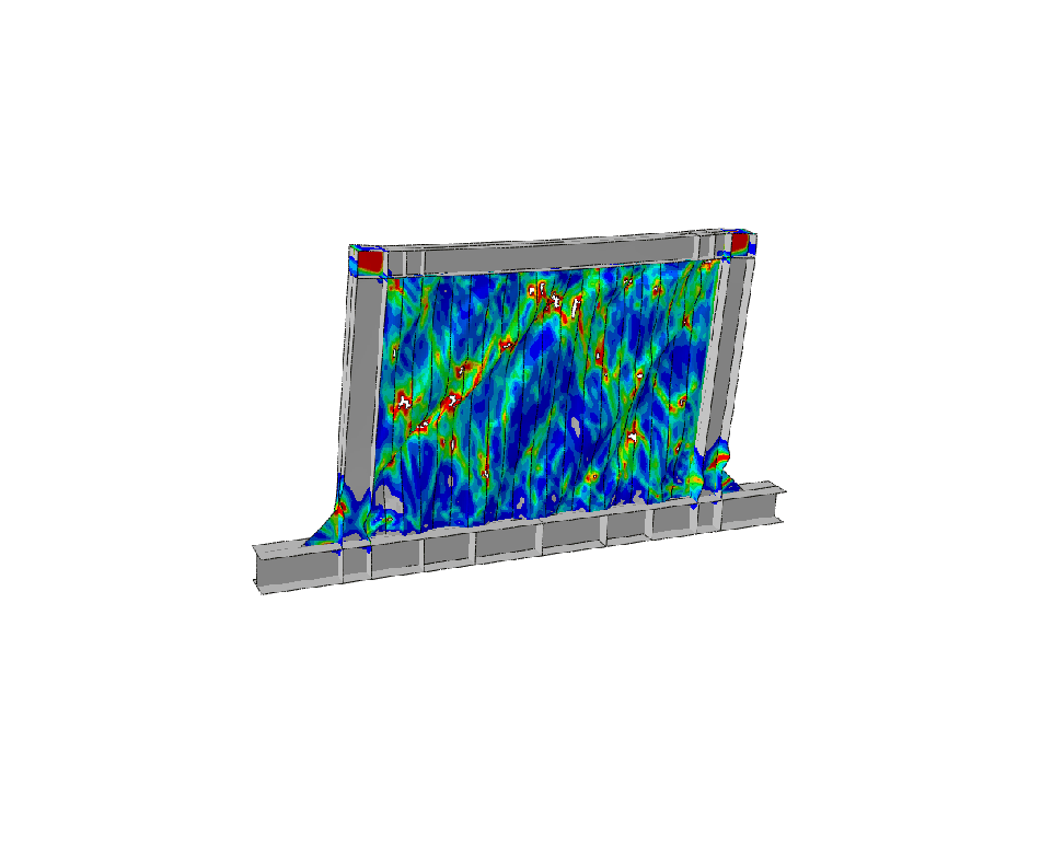
Initially, the press-fit results are presented followed by the results of the transient simulation. The main interest of the press-fit results was in the stress-strain state of both components. During the transient analysis, we were mainly interested in contact stress distribution.
Press-fit

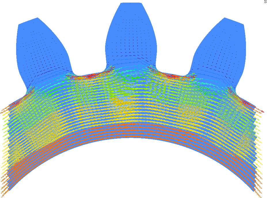
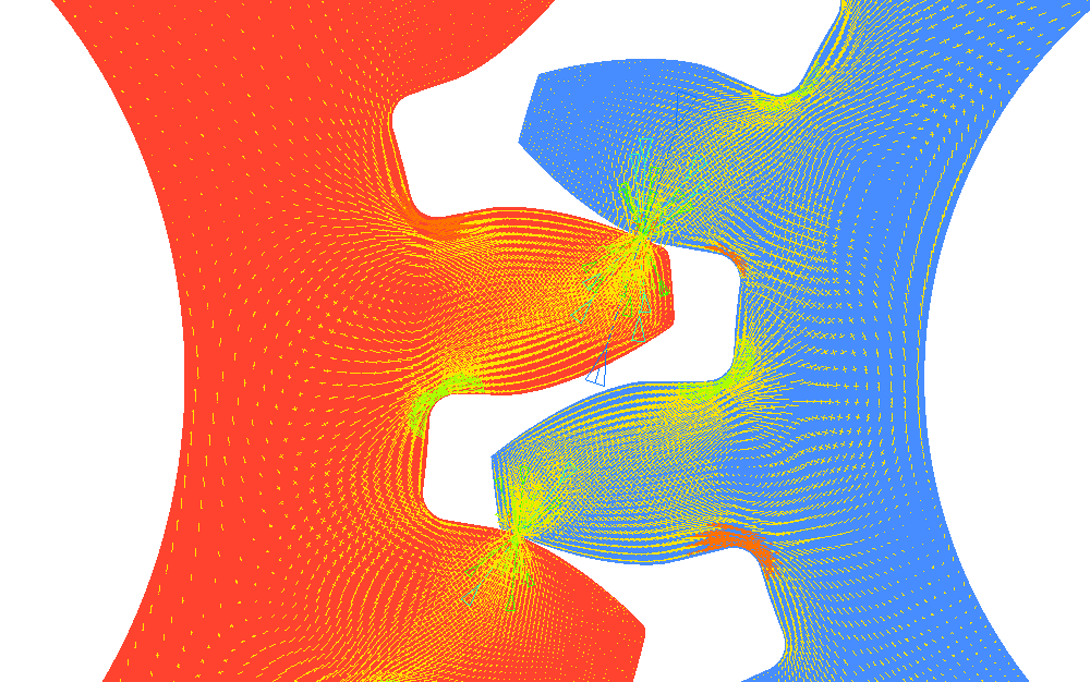
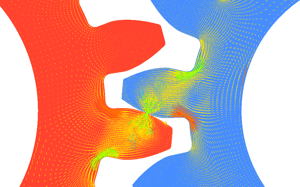
In the press-fit, mainly tensile stresses are present in the gear and compressive stresses are present in the shaft. To see that more clearly principal stresses are plotted in vector form. In Figure 4 it can be seen that the largest stresses occur at the base of the gear. This is because the cross-section there is the smallest.
Transient simulation
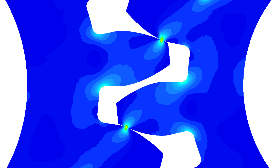
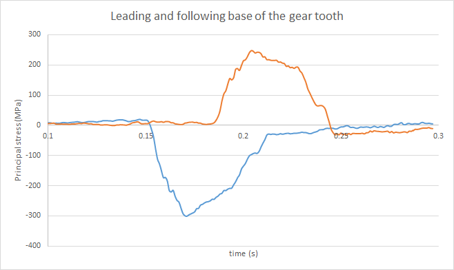
During the transient simulation, the focus was mainly on stress distribution. A main part of stress in gears comes from the contact pressure and bending moment on the teeth. In the beginning, when contact is initiated, not all of the torque is transferred only between one pair of teeth. There is still another pair of teeth in contact. This splits the load among two pairs and results in lower stresses. We can observe that in figure 5.
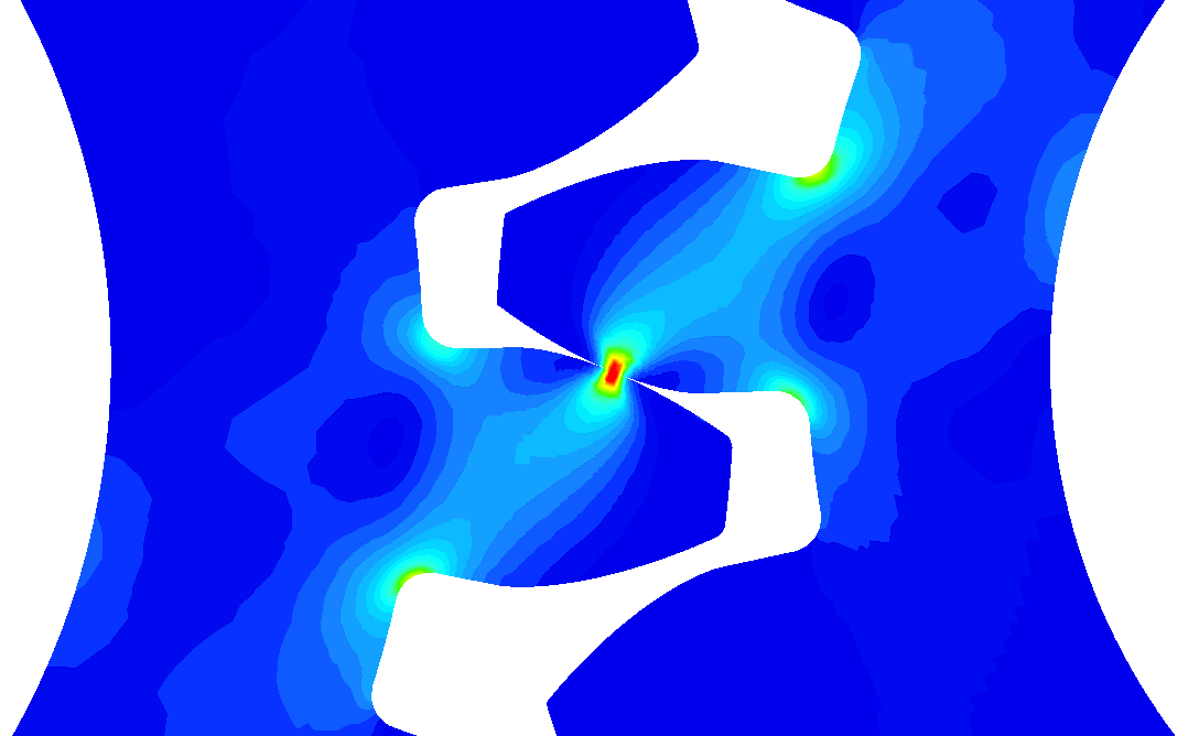
As the gears rotate further, the contact in the first pair of feet is no longer present. This results in a significant increase in stress. Stress distribution can be seen in Figure 6.