Introduction
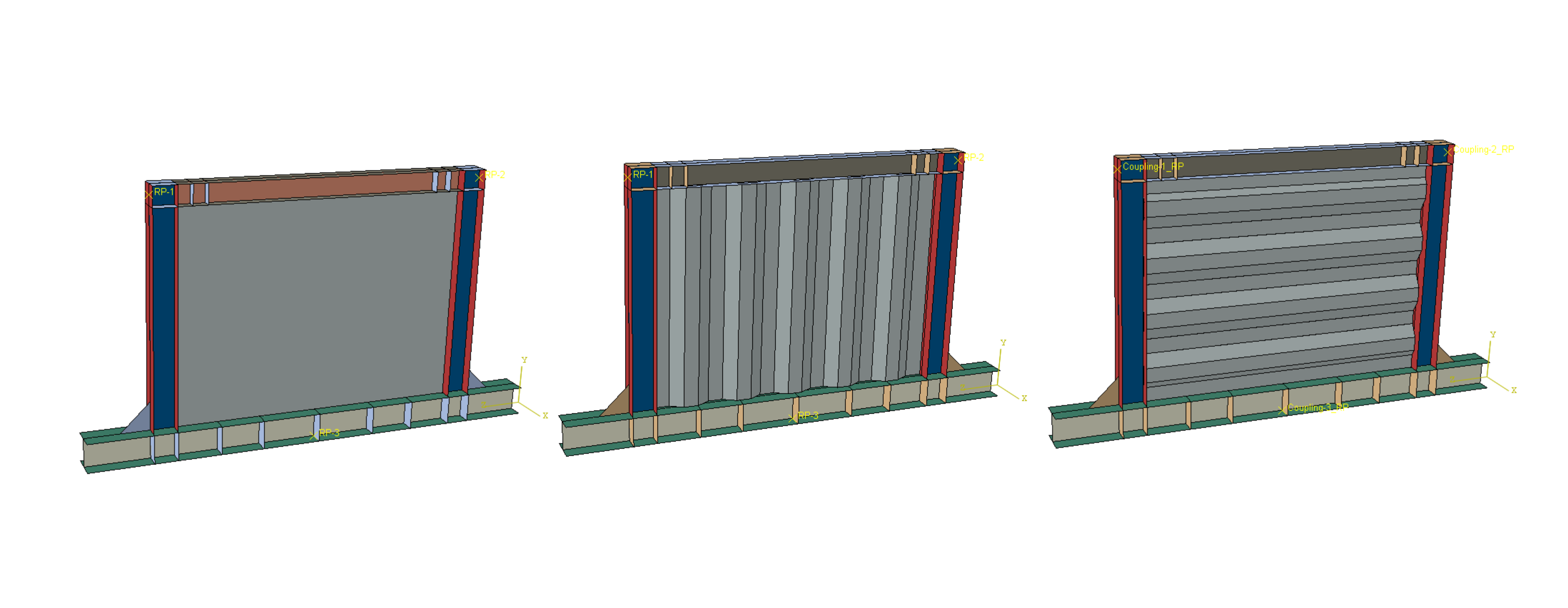
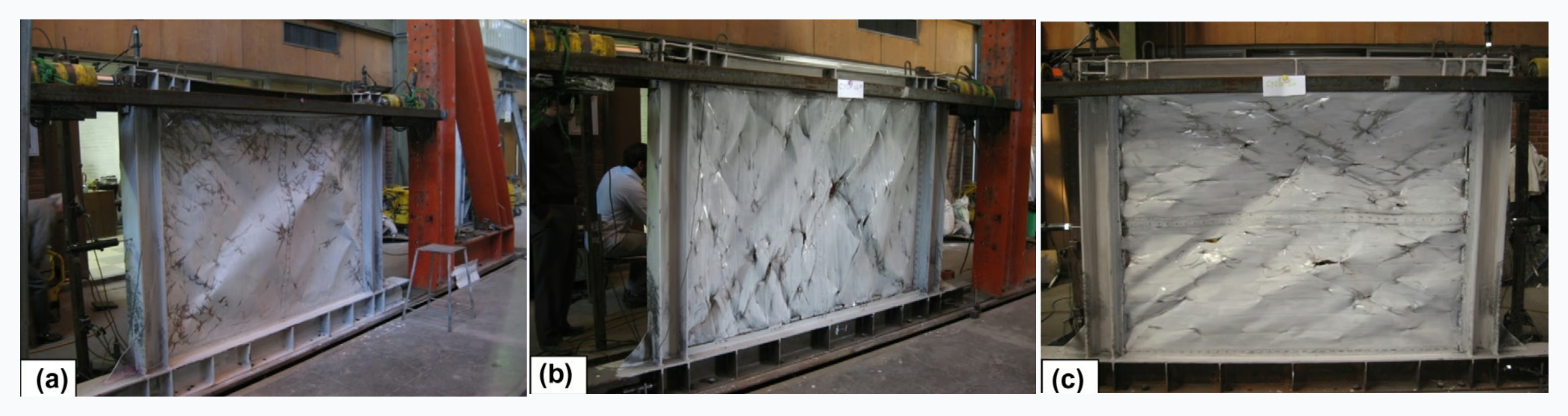
This benchmarking study compares FEA predictions against experimental results for three corrugated steel shear wall specimens subjected to AC154 quasi-static cyclic lateral loading. The three specimens differ in their panel configuration: Specimen A uses a flat (unstiffened) steel sheet, while Specimens B and C incorporate vertically corrugated steel panels with differing corrugation profiles. The experimental program by Emami et al. provides the reference dataset against which all numerical predictions are validated. The objective of this study is to assess the accuracy of the finite element modeling approach in capturing the lateral load-displacement response, energy dissipation capacity, and failure behavior observed during testing. Successful validation of the numerical models against the three specimens — spanning both flat and corrugated configurations — would establish confidence in applying the same modeling methodology to future seismic design applications where physical testing is not feasible.
Input Data and Unit System
The specimen consists of a 1480×1980×1.25mm trapezoidally corrugated panel with HE-B160 columns and HE-B140 top beam. The corrugation features 100mm flat width, 50mm depth, and 30-degree pitch angle running vertically. Material properties from coupon testing show St12 steel panel with 207 MPa yield stress and 290 MPa ultimate stress. Boundary frames use St44 steel with higher strength to ensure capacity design hierarchy.
Material Properties
The steel panel uses elastic-plastic behavior with Young's modulus 210 GPa, yield stress 207 MPa, and ultimate stress 290 MPa. Ductile damage initiation employs criterion with fracture strain 0.8 at stress triaxiality 0.3. Upon damage initiation, linear degradation proceeds until element deletion represents crack formation. Boundary frames use 300 MPa yield for columns and 288 MPa yield for beams.
FEA Model Setup
The analysis uses Abaqus/Explicit approach since a high degree of nonlinearity is observed. Modeling this type of failure and large displacement would result in very small implicit time step, so we found that using Explicit scheme is the right approach for the analysis. The complete structure employs a conforming mesh topology where all components share nodes at interfaces, eliminating contact definitions.
Mesh
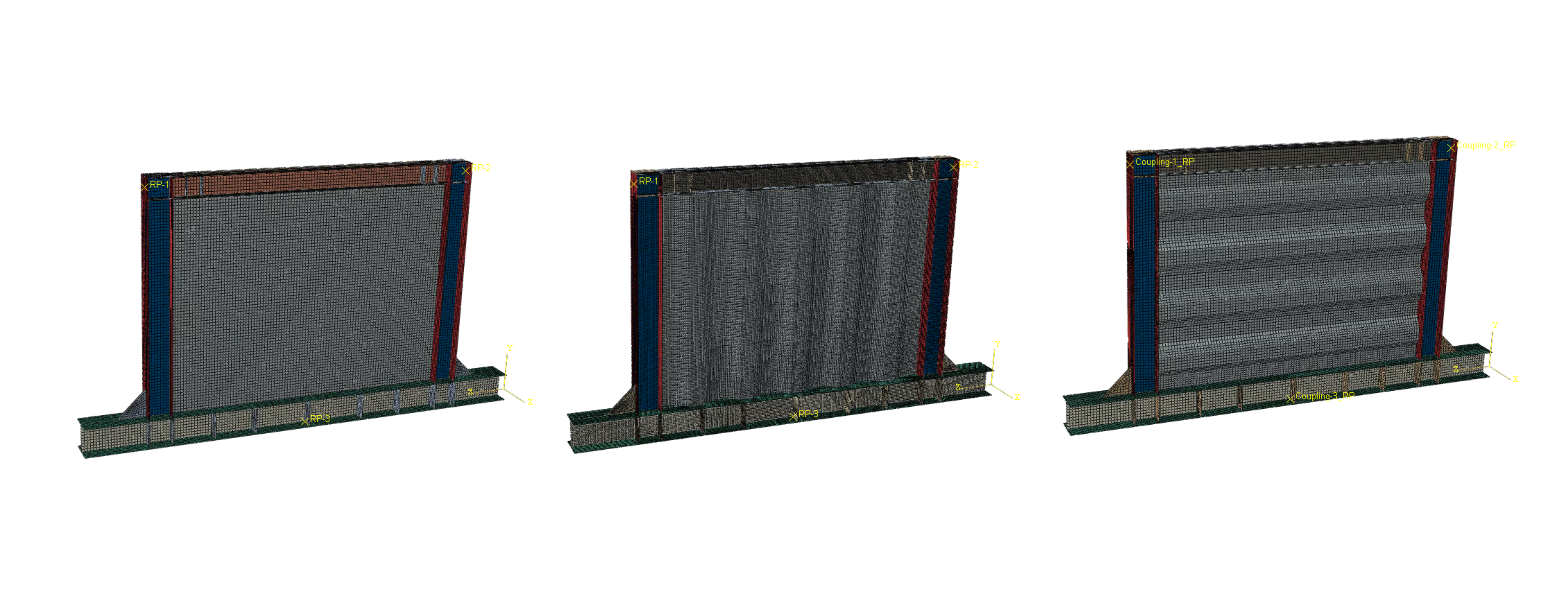
The mesh contains about 58000 nodes and elements using S4R shell elements (4-node with reduced integration) for specimen A. Element size ranges from 5-8mm at connection zones to 10-15mm in frame members. Five integration points through thickness capture elastic-plastic bending behavior.
Loads and Boundary Conditions
Bottom beam bolt holes are fully constrained replicating the experimental boundary condition. Lateral supports at top beam level prevent out-of-plane motion. Cyclic displacement loading follows the AC154 protocol with amplitudes from 5mm to 100mm applied at the top beam, maintaining quasi-static conditions throughout the explicit dynamics solution.
Mass Modeling
The entire structure uses conforming mesh with shared nodes between panel and frame components, avoiding computational overhead from contact algorithms. This approach accurately represents force transfer while maintaining numerical efficiency. Mass scaling below 1% with 2e-6 second timestep ensures quasi-static response without spurious dynamic effects.
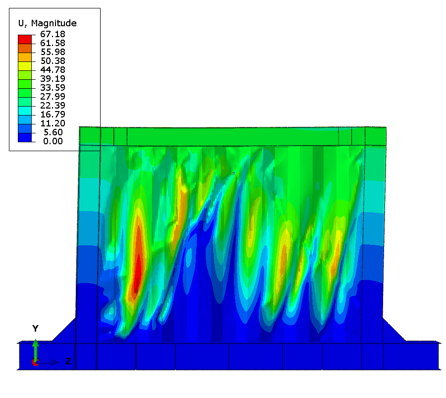
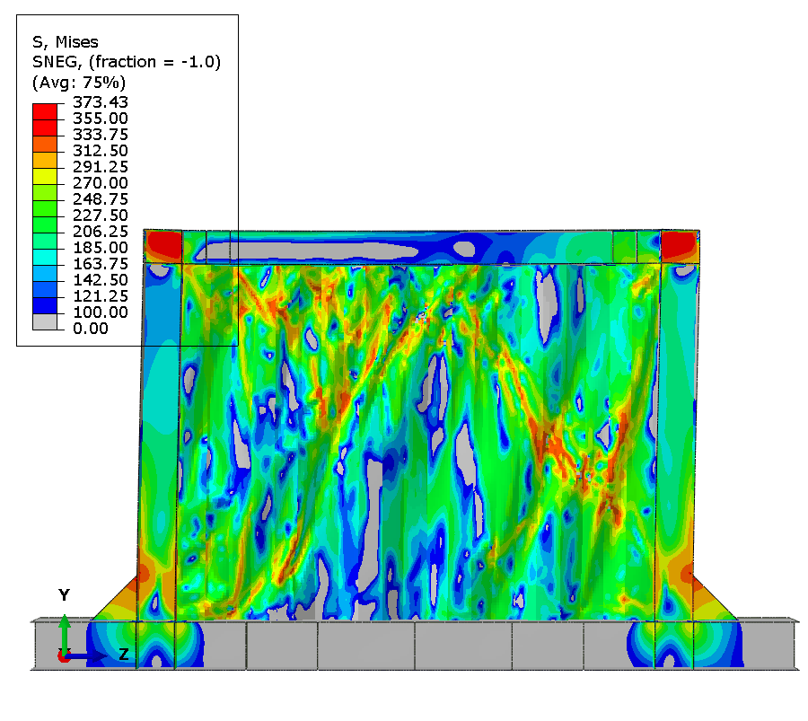
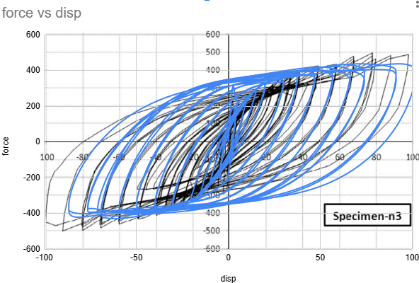
Results - Specimen A
Buckling is observed right after first cycle at 5mm displacement.
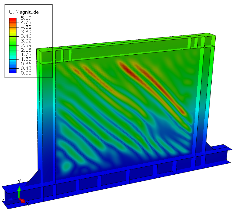
Fracture is observed at the 17th cycle at 60mm displacement.
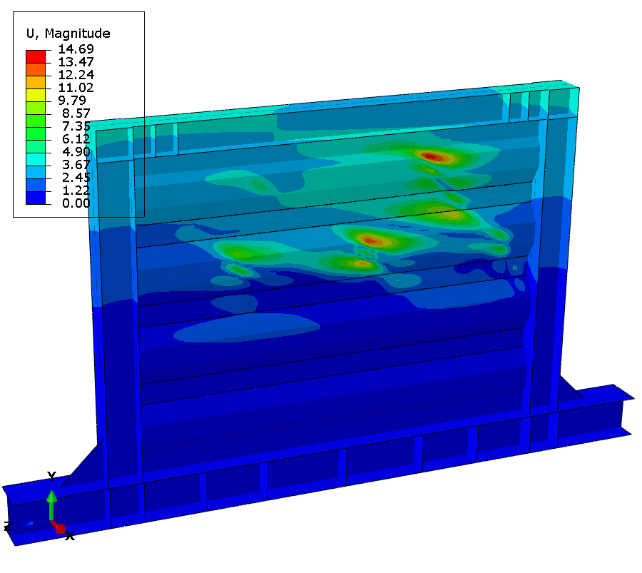
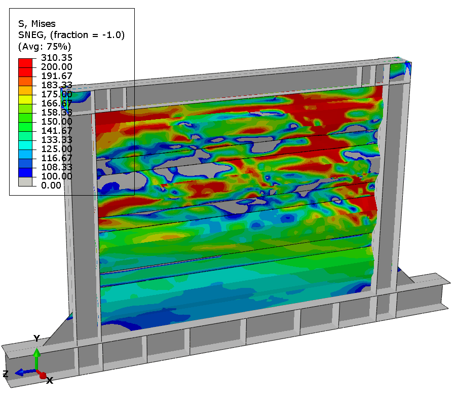
Results - Specimen B
Buckling is observed at 2nd cycle at 5mm displacement.
Fracture is observed at the 10th cycle at 40mm displacement.

Results - Specimen C
Buckling is observed at the 3rd cycle at 5mm displacement.
Fracture is observed at the 15th cycle at 50mm displacement.
Final State and Comparison
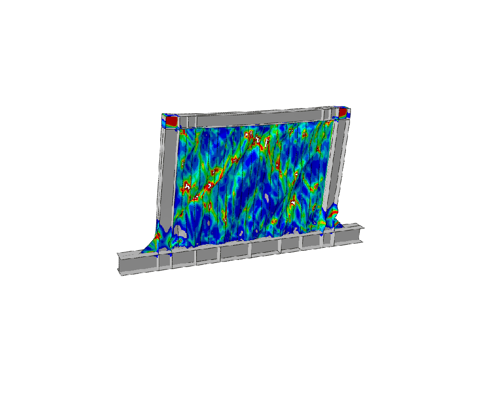
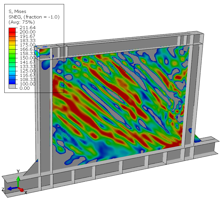
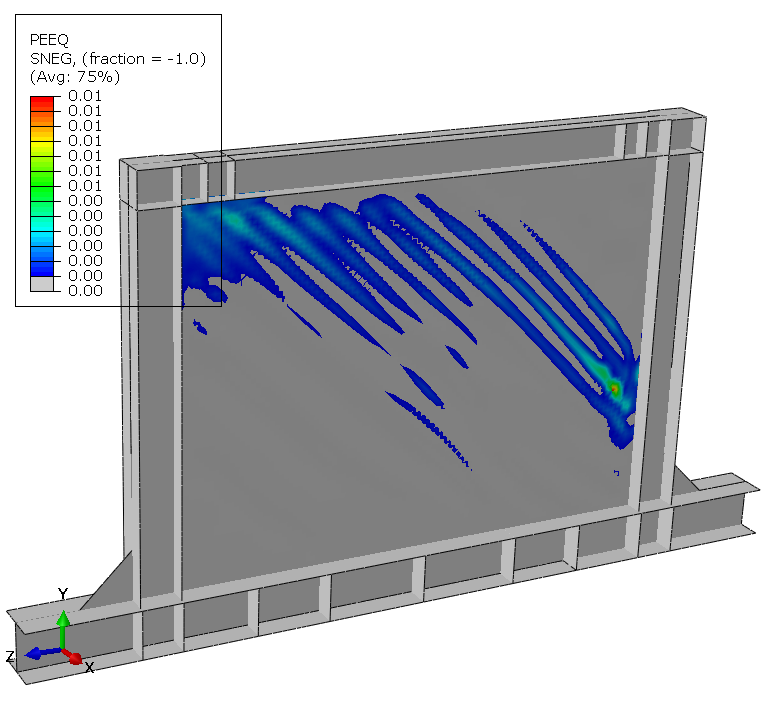
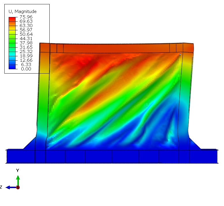
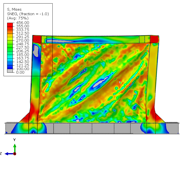
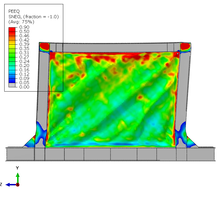
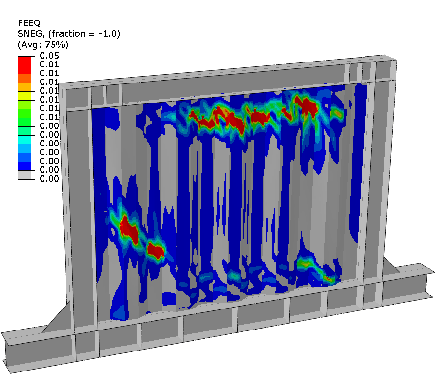
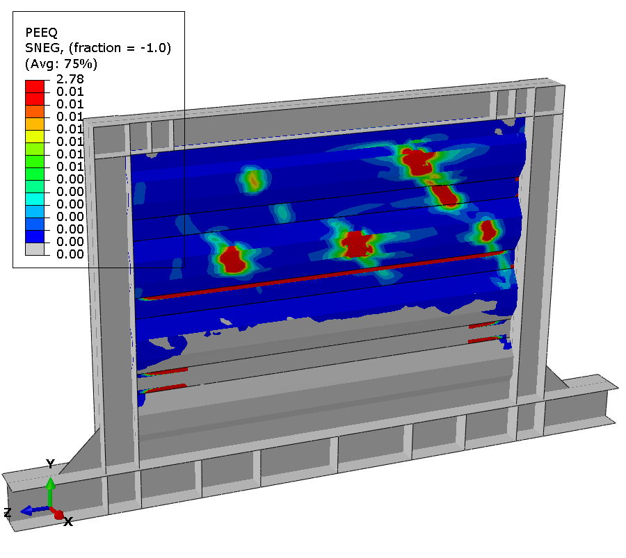
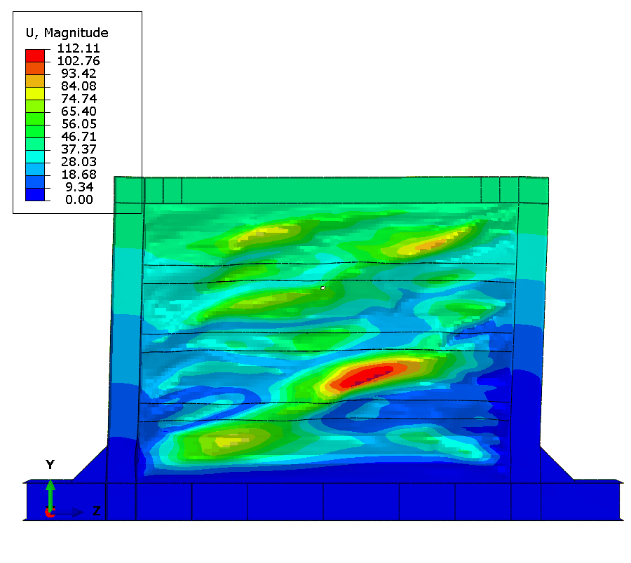
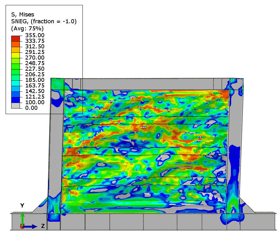
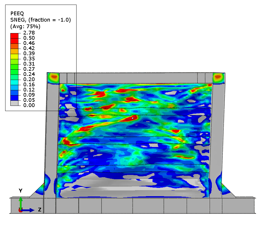
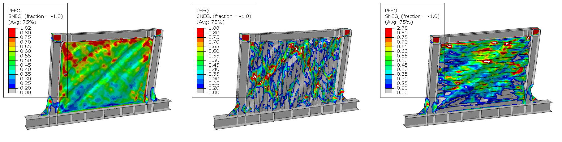
At test completion, extensive damage accumulates throughout the panel. Element deletions representing cracks appear at about 10 discrete locations distributed along tension field diagonals and at geometric discontinuities. Maximum plastic strain exceeds 0.8 in elements adjacent to deleted elements, demonstrating progressive ductile failure mechanism.
Conclusion
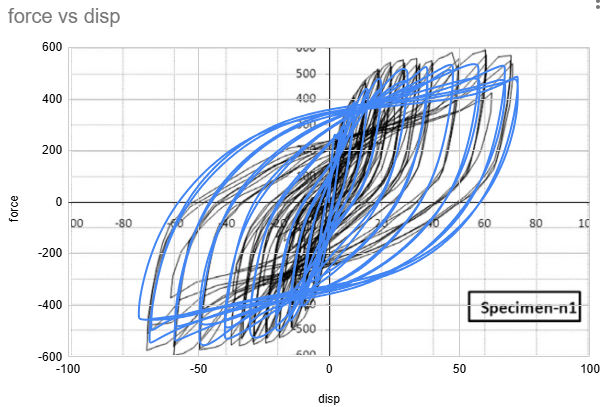
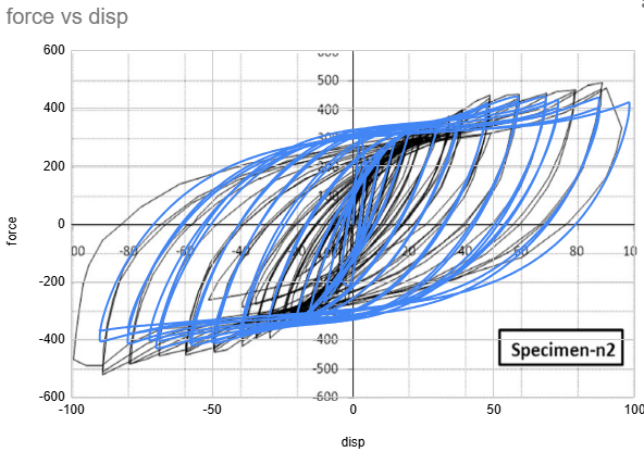
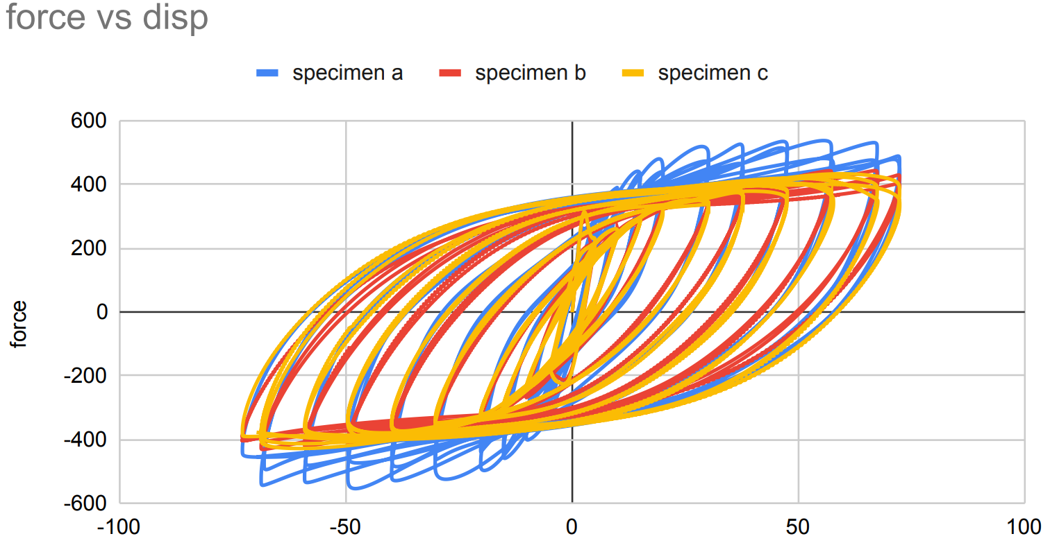
The FEA predictions show good overall correlation with the experimental hysteresis response across all three specimens, with force-displacement curves matching within 10% of the measured data and hysteresis loop shapes closely following the experimental envelopes throughout the loading history. The primary discrepancy occurs during the unloading phase, where the FEA exhibits a steeper slope than observed in testing. This is attributed mainly to the limited material property information available — only yield and ultimate strength were used to define the material model, without implementing kinematic hardening. Kinematic hardening governs the Bauschinger effect and back-stress evolution under cyclic load reversal, and its absence causes the model to overestimate unloading stiffness. The most notable finding is that Specimen A, the flat unstiffened panel, demonstrates the highest lateral load capacity of the three configurations — a result that is counterintuitive given the conventional expectation that corrugation improves structural performance. Investigation into this behavior suggests that the corrugation geometry, while increasing out-of-plane bending stiffness, introduces geometric stress concentrations at the fold lines. Under cyclic loading, these concentrations accelerate local plastification and crack initiation in Specimens B and C, limiting their load-carrying capacity at large displacement amplitudes. The flat panel, by contrast, distributes inelastic strain more uniformly across the panel surface, allowing it to sustain higher forces before degradation becomes significant. This finding has practical implications for the application of corrugated steel shear walls in seismic design, and warrants further investigation into corrugation geometry optimization to mitigate premature strain localization.
References
F. Emami, M. Mofid, A. Vafai, Experimental study on cyclic behavior of trapezoidally corrugated steel shear walls, Engineering Structures, Volume 48,2013, Pages 750-762